Jobsite facilities layout plan: access and facilities
Plan where the jobsite facilities modules will sit, how people and service vehicles will reach them, and where utilities will connect. Use the layout to request a quote that covers the facilities and their installation.
A DXF outline and an inquiry checklist, available without registration.
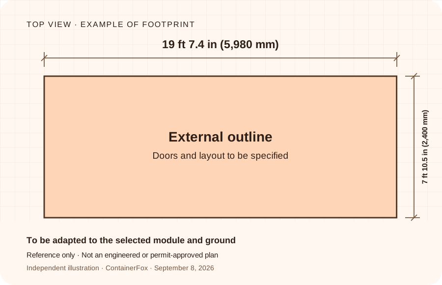
This reference sketch shows one example footprint, approximately 19 ft 7.4 in × 7 ft 10.5 in (5,980 × 2,400 mm). It is not an engineered or permit-approved plan; these dimensions do not apply to every office trailer or modular building.
Two tools to start your plan
Use the outline as a starting point for a sketch and the sheet to prepare your request. The final plan should reflect the dimensions of the model actually proposed.
2D drawing · DXF
A module outline to adapt
Closed rectangle of 19 ft 7.4 in × 7 ft 10.5 in, external dimensions. Annotations are on a separate layer.
Imperial reference: approximately 19 ft 7.4 in × 7 ft 10.5 in. DXF AC1021 (2007) geometry remains in millimeters. Without doors, supports, utilities or clearances; not an engineered or stamped drawing.
Complete the sections on the site, modules, access and services. Use the checklist alongside photos and a site plan when discussing the project with suppliers.
TXT file editable in a text editor, to keep or print.
Use the DXF and obtain the correct DWGCheck the drawing unit, then request the exact plan from the supplier.ExpandCollapse
Open the DXF using millimeters, then measure the long side: it should be 5,980 mm, approximately 19 ft 7.4 in. If your host drawing uses inches or feet, apply an explicit unit conversion when inserting it and verify the measured length. Changing the display label alone does not convert the geometry.
Keep the FOOTPRINT layer for the outline; the ANNOTATIONS layer contains the details. Position the modules on a site plan at the same scale.
Replace this example outline with the dimensioned plan of the selected model, including its openings and connections. Have the supplier specify the supports and handling constraints.
Looking for a DWG block for jobsite facilities? The download offered here is a DXF. Ask the supplier for the native DWG file of the ordered configuration, or a dimensioned PDF. A footprint rectangle is not enough to prepare installation.
Preparing the site layout in 4 points
The plan should show how the modules will be used and how they will reach their location. Include photos to make site constraints visible.
1
The spaces required
List offices, locker rooms, rest and eating areas and toilets with the number of people on site at the same time. Specify what is already available on site and what needs to be added.
2
Truck access and lifting
Identify gates, bends, gradients, overhead obstacles and parking areas. Check the feasibility of unloading and the distance between the truck and the installation area.
3
Ground and circulation
Draw the boundaries of the available area, the doors and the planned routes. Have the ground, levels, supports and access arrangements validated by the relevant parties.
4
Utilities and commissioning
Identify drinking water, electricity and drainage points with their distance to the modules. If self-contained, specify the supply, refilling, tank emptying and servicing visits.
Toilets and washing: locate handwashing and toilets to meet the governing workplace rules. Specify water supply and temperature, soap, drying and any permitted alternatives or task-specific washing requirements.
Breaks and meals: plan a suitable break area. Federal construction sanitation rules prohibit eating or drinking in toilet rooms or areas exposed to toxic material; they do not by themselves require every site to have a heated break trailer or kitchen. Check additional applicable rules and project needs.
Changing and protective clothing: identify task-specific triggers. Under the federal construction sanitation rule, specified toxic-contamination protective-clothing requirements trigger change rooms with separate street-clothes and protective-clothing storage. Check shower, drying and other needs under the applicable standards.
Access throughout the shift: consider the most remote work area, lighting, pedestrian routes, gates and actual opening hours. Keep exits and escape routes unobstructed when structures are occupied. Add satellite or mobile facilities if travel makes central provision unsuitable.
Servicing and moves: allow the servicing vehicle to reach tanks safely. Show replacement facilities during relocation and keep provision until the work ends.
Record the agreed facility arrangements and responsible parties in the site's health and safety planning. A supplier's module footprint alone does not show whether the facilities are sufficient or accessible.
A module advertised as '19 ft 8.2 in' may have different dimensions and equipment from another. Request the document corresponding to the reference proposed in the quote.
Dimensions and openings
External and internal dimensions, height, partition layout, location and opening direction of doors.
Installation and assembly
Support, lifting and fixing instructions, junctions between modules and specific arrangements in case of stacking.
Service connections
Position of inlets and outlets, powered equipment, preparations to make and work included in commissioning.
The download is an illustrative rectangle; its dimensions do not establish a US product specification. The outline does not represent usable interior floor area, a manufacturing drawing or an engineered design. Ask the reviewing authority which site, building, trade and installation approvals apply to the actual location and use. OSHA workplace planning does not grant placement or building permission.
What is often missing before ordering
Doors and passageways: a group of modules may fit on the site while obstructing movement or door opening.
Ground preparation: having a module delivered does not mean that supports or earthworks are included.
Connections: specify who carries out trenching, connections and pre-use checks.
End of rental: keep access for removal and allow for disconnection, cleaning and collection in the budget.
Validate the site layout for your projectEquipment, circulation and installation conditions should be checked with the project managers.ExpandCollapse
Have the configuration and its siting reviewed with the site managers and the supplier: staffing levels, hygiene, access, emergency provisions and site constraints. The downloadable outline and the preparation form do not constitute regulatory or technical approval.
Send suppliers the same requirements and site constraints. You will be able to distinguish the price of the modules from the cost of their installation.
Get a quote for each service
Modules + transport + unloading and installation + ground preparation + connections.
Add maintenance and end-of-rental collection. For each item, request an amount, what is included and who is responsible. Include your preferred date and delivery ZIP code.
Can I download a jobsite facilities plan for free?
Yes. The reference footprint is approximately 19 ft 7.4 in × 7 ft 10.5 in. The DXF retains millimeter geometry; the SVG and checklist include the imperial reference. These are preparation tools, not engineered, stamped or permit-approved plans. Use the actual selected module and site dimensions.
Is the file provided a DWG block?
No, the drawing file is an AC1021 (2007) DXF, declared in millimeters. For a DWG, ask the supplier for the native plan of the exact model proposed in the quote. Always check the dimensions and scale after opening or inserting a drawing.
What should the installation plan show?
The location and actual dimensions of the modules, the openings, the routes, delivery access routes and the connection points. Supports, handling and site constraints should be specified with the supplier and the relevant parties.
Are the dimensions 19 ft 7.4 in × 7 ft 10.5 in universal?
No. These are for a sample module. Other models may have different dimensions. Use the layout plan of the actual model ordered before preparing the supports or installation.
Who prepares and approves the layout plan before delivery?
Ask the supplier for the layout plan and instructions for the proposed model. Site positioning and installation planning must be coordinated with the site managers. The quote should specify who prepares the ground, carries out the connections and arranges installation.